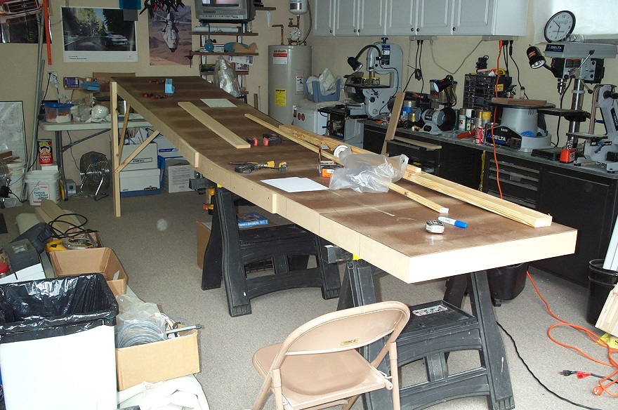
The Fuselage Started by constructing multi purpose Partial Molding Tables, frame is 3/4 MDF cut 4″ wide, skinned with 3/16″ hard board, the Sky Jump Ramp allows the fwd to aft transition curvature (section built the same way) to be molded in. table tops are covered in clear packing tape

After a down select process a hot wire foam lower fuse radii “block mold” was selected, once attached to the table with drywall screws it got coated with duct tape. The raised duct tape pad is to provide an inward joggle for the wing box connection outside plies
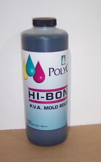
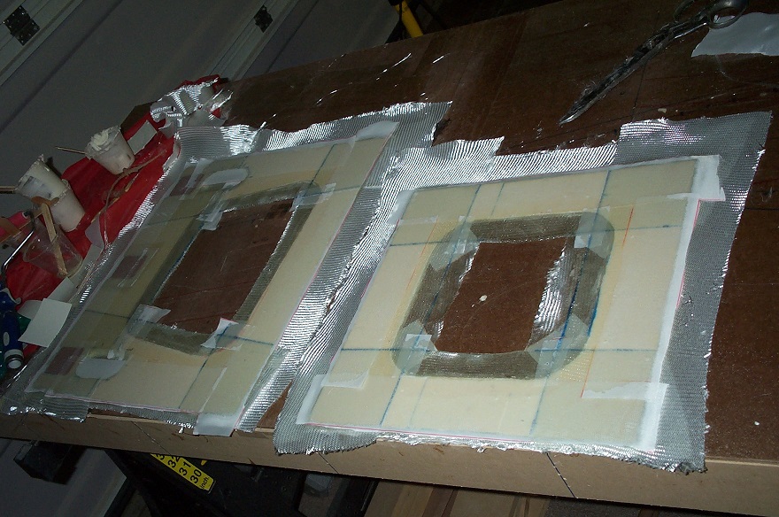
PVA Release Agent coats all parts of the tooling that will make contact with the layup.

After the PVA, Peel Ply is applied to all areas of the tooling that the layup will make contact with.

Foam Core is nailed to the hard board skins with 4 penny finish nails, all cutting & ramps processed in advance. as needed with any foam core a complete Vacuum using a brush attachment is in order to pull up all loose foam dust.

Micro / Epoxy is applied to the foam, the viscosity needs to be thin enough for the slurry to make it into the pours of the foam. Many who complain about LAF forget to do the Vacuum & Micro steps, these are key to make an airworthy part.
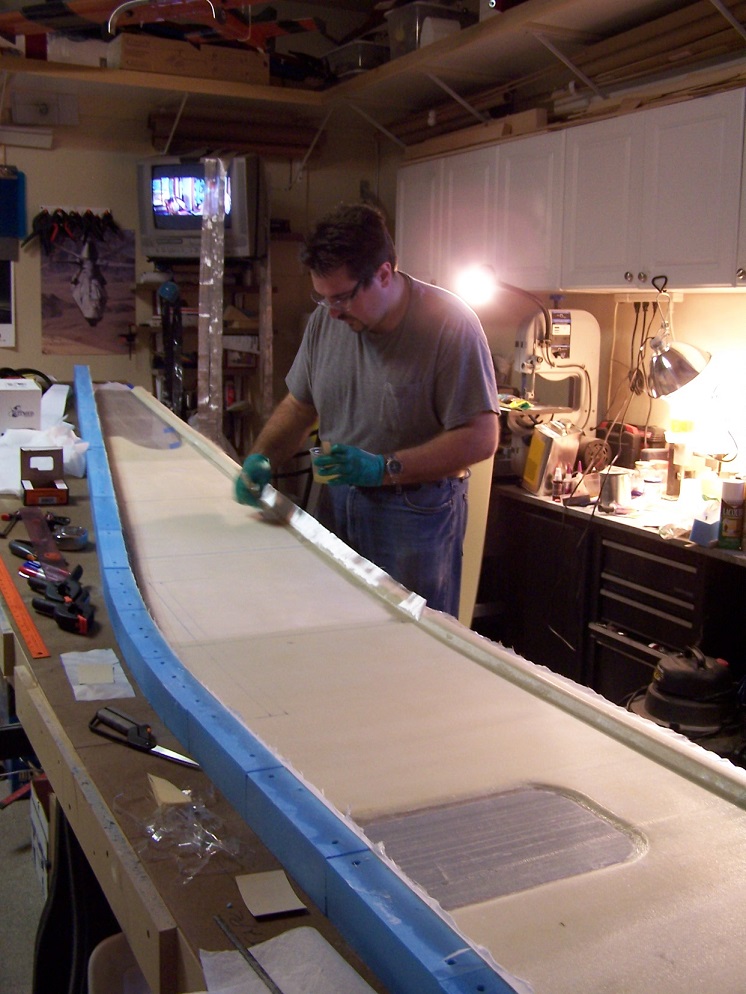
Layup in process, Back in more more innocent days, now days I never use any high power chemical product like E-poxy with out a full cartridge respirator

If you use e-poxy regularly like I have since 1993 you need to have the right protection, Niosh rated cartridge respirators are low cost & available from the Box Stores

Finished layup on the inboard side.

Both left & right sides free from the tooling, a quick 1st opportunity to sit in the fuselage and make airplane noises. even though the sides are upside down in this pic

The table is simply inverted with some stand offs added to layup the outside of the fuselage. On larger runs I always roll the fabric kits up then un-roll them on the laminate to limit the fabric distortion & snaging.

Finished outside layup overview

Close up on the layup showing the snake scale look you should see in a correctly done wet layup.

Bottom skin is the next item, at this point its at the core shaping stage. Note I’m not a die hard fan of Last A Foam, I’ve done trials on Divinycell & Roahcell and for the methods used on this kind of construction they would all work.

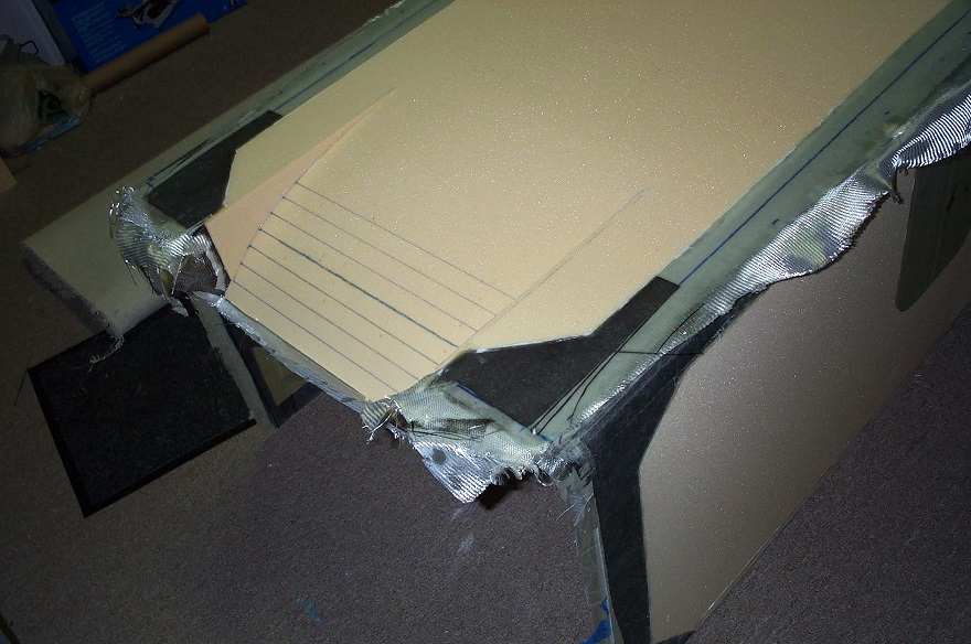
Engine Cowling exit air ramp, pre processed in the lower skin.

Finished lower skin inboard surface on tool. Transition Radius section was close enough on the lower skin to re use the sides transition section.
preliminary un trimmed fit on sides

The internal Fire-Wall structure, will feature same thermal protection after this point as a Velocity, Ceramic blanket with SST or Galvanized fire wall outer skin. the corners and sides are Phenolic sheet, not to long after this pic I learned about a way better pre-made sheet laminate hard point material. Phenolic is not to bad for a Firewall application due to its thermal capability.

Up to this point I only knew Phenolic as a Non Wood alternative hard point with good bond capability, William Introduced me to Arnold Holmes “The Repair” he worked may of the V8 Lancair projects with William, Adam Aircraft and other Composites Jobs, he introduced me to G10 pre-made fiberglass sheet. After learning about this material & what it could do it was another jump forward for me in Composites. Arnold is now at http://www.av-mech.net/
some of the other bulk heads in the peel ply / pre-trim stage.

Just starting to get mileage out of the tooling tables, now both flat sections are bolted together on the floor with a center line added getting ready for Fuselage alignment & bonding.

Initial alignment of sides and bulk heads,

Bulk heads are attached top / middle & bottom with dry wall screws for initial alignment. Roving was used as the fillet (very clean / higher strength than micro for a long run) connection tapes are processed via the plastic / flat pattern transfer method.
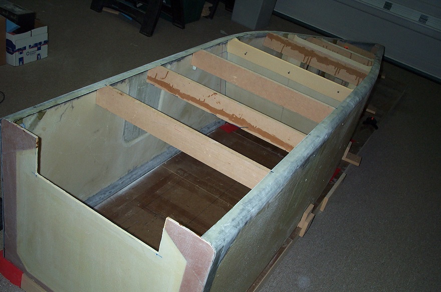
Additional temporary support board are added for the bottom skin, they will keep the lower skin true while the outside layup is processed while the fuselage is in this configuration.

Top Skin bonded using 1/8″ Copper waxed Clekos and PTM&W structural epoxy adhesive.
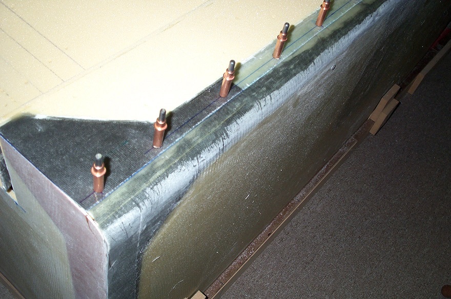
zoom in of the Cleko bond setup, all extra epoxy on the outside cure was squeegy up for a clean bond.

Tail view of the lower skin bond, the cleats that attach the sides to the tooling tables are also shown.
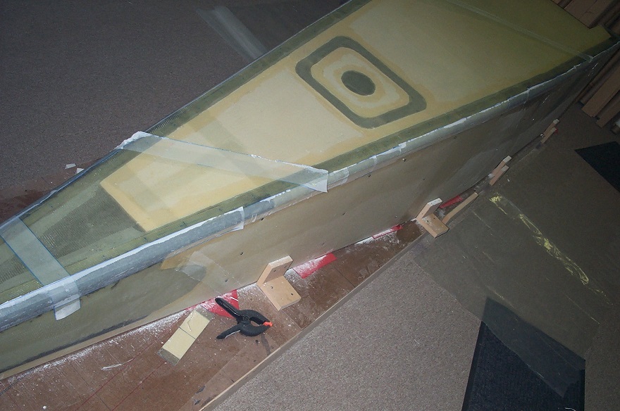
Clekos removed, edge fill / sand completed and lower skin outer layup processed. Once a full sandwich structure the bottom skin is ridged and no longer needs the lower temp support boards.

I loaded up the Fuselage and took it over to the Fly Corvair hanger to show William & the guys.

William tries on the 500, Rick Lindstrom’s Corvair powered 601 in the background.

Whobis Cat the Edgewater hanger gangs official mascot inspects the internal layups & bonds.

None of that crammed like a sardine non since in this plane, i.e. what fills most of the Aero Crafter Kit plane Catalog.
